Week 4 Problem Set
PSET #4
ASSIGNED: Friday 01 May 2020
DUE: 5:00p Pacific 08 May 2020
NOTES:
- Given the unique circumstance of Spring 2020, we ask you to do your best to maximize your learning. Each problem set is an opportunity to assess your learning, identify gaps, reflect on what you have learned, and determine what you wish to learn next.
- You can discuss the PSET questions with other students. But your answers should be your own work. Please let us know if you collaborated with other students working on the PSET.
- Please turn in your completed problem sets as an electronic copy via Gradescope. Please make sure to clearly indicate the starting and ending boundaries of your answers to each question on Gradescope.
- Please do not go over any word limits and where appropriate show your work (e.g., calculations with appropriate units).
- Please type your answers when possible.
- Please label and provide descriptions for the figures.
GOAL: Reflect on the role of Abstraction as a tool for helping to manage complexity in biological systems.
(Q1) Generic System Architecture (25 pts)
In class you encountered the Generic System Architecture composed of:
- Sensors (to measure properties or inputs),
- Logic Unit (to process information measured via sensors), and
- Actuator (that can act or output the desired result).
We can apply this same architecture to abstract a diversity of systems. For example, imagine yourself riding your bicycle on University Avenue and encountering a stop sign.
In one scenario you can describe yourself as the system. In this case, your eyes are the sensor, your brain is the computation unit, and your hands are the actuator (i.e., pressing the levers to stop your bike).
In another scenario, you can describe your bike as the system. In this case, the levers are the sensors. There is no computation unit, and the signal is directly transferred via a cable to the brakes (i.e., actuators on the wheels).
Q.1.a. Look around the world from the perspective of an integrated systems engineer. Find an example of an integrated system, either natural or engineered. Submit a photo of the system you found and provide a one line description of the system itself.
Q.1.b. Draw the generic system architecture with appropriate units for your system. Label the input(s) and output(s) to the system. What signals are used as inputs and outputs (Add units if appropriate)?
Hint: Do your best to draw a clear and easy to follow diagram.
Q.1.c. Revisit Acoustic reporter genes for noninvasive imaging of microorganisms in mammalian hosts paper.
This paper introduces a new class of reporter genes, akin to fluorescent proteins but different. Intead of taking in one waverlength of light and emitting a different wavelength (e.g., green fluorescent protein) these genes are activated by sound of a particular frequency and scatter the sound waves, creating a signal that can be detected by an ultrasound scanner. Thus, these genes allow the creation of a new family of actuator devices, wherein a transcription signal and sound are the inputs and scattered sound waves are the output. Draw a transparent black-box diagram that correctly notes the input and outputs for such an acoustic reporter device. Please show the exact device boundary between PoPS-source and ribosome binding site for the first open-reading frame (ORF) in the acoustic reporter device. Please also show the sound and scatter input and output.
Note: If you want to learn more about abstraction, sensors, and actuators in living matter check out BIOE 44: Fundamentals for Engineering Biology Lab
(Q2) CHOMP Circuits (25 pts)
Referring back to class, recall the hierarchy based on the Part (bioparts), Devices, and Systems approach to abstraction. If you need a refresher, please use the following link.
Q.2.a. In your own words, provide a 1 sentence definitions for Parts, Devices, and Systems.
Briefly read the abstract from the paper titled: Programmable protein circuits in living cells.
Q.2.b. In your own words, summarize the abstract in 2-3 sentences. What is the main claim of this paper? (1-2 sentences)
Q.2.c. What are the primary evidence in support of the claim?(1-2 sentences)
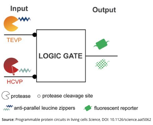
Q.2.d. Take a look at Figure-1 below (reproduced from the paper). Briefly describe what are the inputs and the output to this logic device? (Bullet points)
Q.2.e. Does the presented logic device (Figure-1) use a Common Signal Carrier? Why or Why not? If the logic device does use a Common Signal Carrier, what is the common signal carrier? (Bullet points) (Hint: We define Common Signal Carriers from a very formal engineering perspective in this class; specifically, any output from a device must manifest via exactly the same type of physical variable or process as any input to the device)
(Q3) Plants with Genetically Encoded Autoluminescence (50 pts)
First read the abstract of the paper titled Plants with Genetically Encoded Autoluminescence.
Q.3.a. In your own words, what is the main claim of this paper? (2-3 sentences)
Q.3.b. In your opinion, what are the paper’s strengths and significance? What are the paper’s shortcomings and deficiencies? How can the paper improve? (2-3 sentences)
Q.3.c Estimation problem - Let’s try and estimate the total amount of light that an engineered plant could make via an engineered luminescence system. How many watt-hours of illumination should we expect from a glowing plant, per day? What is the potential upper limit?
(Use the following hints)
-
First use the U.S. Solar Radiation Resource Map to look up the average light-energy hitting the surface of the earth (say in California). Your number should have the unit of watt hours per m^2 per day.
-
Next, assume that a plant has a surface area of 1 m^2 and it has 1% photosynthetic efficiency. (This is the fraction of the total energy that gets converted by plants into useful biochemical energy)
-
Finally, assume 5% efficiency for the luminescence system (this is the fraction of the available energy that gets converted into light)
Q.3.d Your have received a special commission to bioengineer the control program for glowing plants.
Specifically, you need to design an integrated genetic system, built from reuseable genetic devices, that implements the following program:
- When daylight is NOT present AND only in cells comprising the flower’s stamen filament then plant autoluminscence should be ON. Please note that cells comprising the flower’s stamen filament can be uniquely identified because they contain two active transcription factors, thorny AND slender.
Draw a system’s level diagram that implements this glowing plant.
Extra Estimation problem (0 points) Let’s consider the specific plants reporterd in the paper. The paper states that the plant emits lights reaching up to 10^10 photons per minute. Looking at Figure-1.a, you may assume that the emitted light has a wavelength of 525 nm. How many watt-hours of illumination per day do you expect from a glowing plant presented in the paper? (Hints: You will need to use Planck constant and speed of light to calculate a photon’s energy for a given wavelength)
Extra resources, learning, and Practice Questions
The following suggested reading and questions are 100% optional additional. They are meant to help you engage with various aspects of the topics that we have covered in each segment based on your interest and level. They are not required as part of your problem sets. But we hope that they enable you to enhance your learning based on your interest.
Q.EX1.Navigating the Abstraction Hierarchy (0 pts)
Recall from the class that we can use abstraction to help and manage complexity in engineering biological systems.
Q.EX1.a. Imagine an engineered living system with a function of your choice. What does this system do? Example engineered bacteria (E.coli for example) to detect lead or arsenic and produce a color pigment (red for lead, purple for arsenic) (1-2 sentences)
Q.EX1.b. Sketch a black box “device-level” systems diagram that would implement your system.
Hint: Your boxes should have simple names, such as “change color,” “detect lead,” “OR,” or whatever human-defined functions are needed and appropriate. Make sure also to connect each black box device to the others as needed.
Next, going down the abstraction hierarchy, you need parts. Where to get parts? How about a student-produced collection of thousands of DNA parts. Sure! Go to the iGEM Parts Registry.
Q.EX1.c. Find parts that could be used to implement your device. Share the name of those parts as part of PSET-3.
If you can’t find what you need, make a note and move on.
Q.EX1.d. Sketch how your parts should be organized as DNA elements in relation to one another so that they would implement the function as you desire. Draw a black box around your parts. Add inputs and output arrows to the box as appropriate. Are your input and output signals generic or specific to your device?
Q.EX2. Buggy Bacterial Flash Mob? (0 pts)
Students at MIT are claiming that they have designed a genetic program to realize arepeating bacterial flash mob. See their work yet again via:
In an epic East Coast versus West Coast technology “battle,” some of your colleagues are now claiming that the genetic program designed at MIT won’t actually produce the so-desired behavior. Looking only at their proposed “device-level system diagram”…
Q.EX2.a. What do you think? Will their program work or not?
YES or NO (circle one)
Q.EX2.b. Why or why not? (bullet points)
(EX3) Unknown genetic circuit (0 pts)
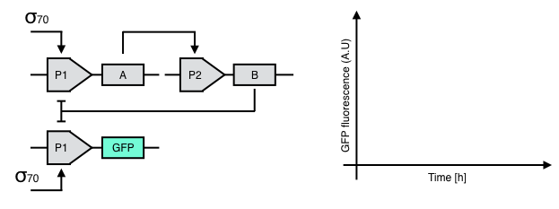
Take a look at the following, genetic circuit.
Q.EX3.a. What are the circuit input(s) and output(s)?
Q.EX3.b. Complete the following time trace diagram. What happens to the GFP signal after $\sigma70$ is added to the circuit? Explain your answer.
Q.EX3.c. Describe the behavior of this circuit via a name (e.g., AND gate, NAND gate, Toggle switch)?
(EX4) Toggle switch (0 pts)
The toggle switch is a common network motif that can be implemented as a genetic circuit. Two inputs are used to switch the system between two stable states. A diagram of the gene-regulatory network is shown below.
A transcriptionally represses B, while B transcriptionally represses A. B also represses the reporter molecule C. SM1 is a small molecule that allosterically inhibits repression of B by A, while SM2 is a small molecule that allosterically inhibits repression of A by B.
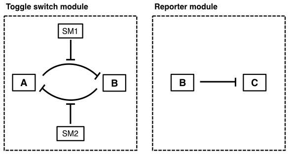
Q.EX4.a. Describe the overall behavior of the system. What are the inputs? What are the two states? How does the system state respond to the given inputs?
Q.EX4.b. A toolkit of biological parts is shown below:
| Part name | Description |
| tetR | Repressor from the tet operon |
| tetO | Operator from the tet operon |
| doxycycline (dox) | Small molecule that binds to tetR |
| lacI | Repressor from the lac operon |
| lacO | Operator from the lac operon |
| IPTG | Small molecule that binds to lacI |
| GFP | Green fluorescent protein |
Using this toolkit, label the gene-regulatory network diagram with the corresponding part names by answering the following questions. (Note: You should choose parts that can work together to achieve the overall system behavior you described in Q.4.a.)
- What part did you assign to A?
- What part did you assign to B?
- What part did you assign to C?
- What part did you assign to SM1?
- What part did you assign to SM2?
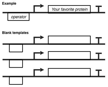
Q.EX4.c. Use the toolkit and the DNA templates below to implement the toggle switch according to your labeled gene-regulatory network from Q.4.b.
github source code for teaching staff